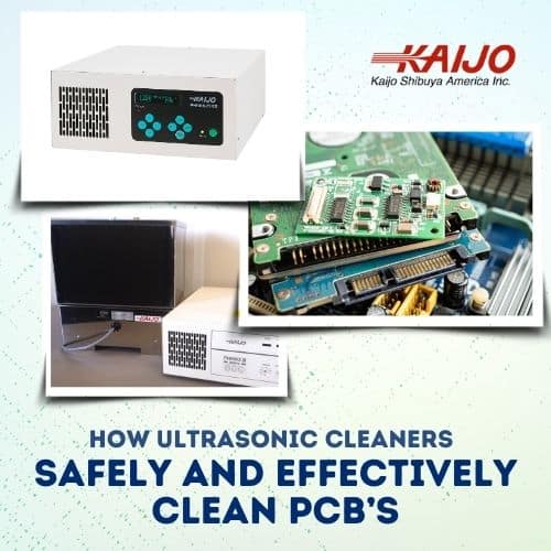
Ultrasonic Cleaner for Electronics Manufacturing
An ultrasonic cleaner for electronics removing flux residues, solder paste, ionic contamination, machining oils, and particulates from printed circuit boards and electronic assemblies, reducing rework, supporting IPC cleanliness standards such as IPC-J-STD-001 and IPC-TM-650, and preparing surfaces for conformal coating across industrial controls, automotive systems, and power electronics production.
 Why Ultrasonic Cleaning Is Specified for Electronics Manufacturing
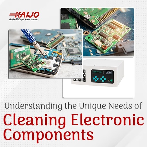
PCB miniaturization and increasing component density have outpaced what manual cleaning and spray-wash systems can reliably achieve. Low-standoff surface-mount devices, microvias, and tightly spaced IC pins create geometry that spray nozzles cannot reach. Ionic residues left behind in these areas are corrosive — they degrade insulation resistance, accelerate electrochemical migration, and shorten assembly service life.
Ultrasonic cleaning addresses this directly. Full immersion means cavitation energy reaches every surface regardless of geometry, without mechanical contact that could damage delicate components. The result is a validated, repeatable process that reduces rework cycles, supports IPC cleanliness documentation requirements, and aligns with lean manufacturing objectives.
An ultrasonic cleaner for electronics extends this capability across connector bodies, precision housings, power modules, and hybrid circuits — not just populated PCB assemblies.
Not sure if your current cleaning process meets IPC cleanliness standards?
Request a Free Consultation with Kaijo’s Experts
How Ultrasonic Cleaning Works
At the core of ultrasonic cleaning is cavitation, the rapid formation and collapse of microscopic bubbles generated by high-frequency sound waves passing through a liquid. As these bubbles implode against contaminated surfaces, they release focused energy that dislodges flux residues, ionic contamination, oils, and particulates from surfaces that conventional cleaning methods cannot reach.
The frequency of the ultrasonic signal determines bubble size and energy intensity:
- Low frequencies (26–38 kHz) produce large, high-energy bubbles suited to heavy contamination on durable assemblies
- Mid frequencies (78 kHz) produce moderate bubbles that clean densely populated assemblies gently without the energy intensity of lower frequencies — and penetrate blind holes, crevices, and tight geometries more effectively
- High frequencies (100–160 kHz) produce small, low-energy bubbles suited to precision components, sensitive configurations, and wire bonds where any excess cavitation energy creates damage risk
Selecting the correct frequency for the assembly being cleaned is the single most important process decision in ultrasonic electronics cleaning.
An ultrasonic cleaner for electronics manufacturing is fundamentally different from spray washing or manual scrubbing. It is a physics-driven, non-contact process where energy reaches every surface the liquid touches.
Electronics Manufacturing Applications
Ultrasonic Circuit Board Cleaner for Assemblies and SMT Boards
Ultrasonic cleaning is a widely adopted and proven method for removing flux residues from printed circuit board assemblies after soldering. Ultrasonic cleaning is used in production validation across bare boards, populated assemblies, SMT configurations, mixed-technology boards, and high-density interconnect (HDI) designs. For detailed process parameters, guidance on frequency selection, and contaminant-specific cleaning protocols, see Kaijo’s dedicated ultrasonic circuit board cleaner resource.
Cleaning objectives:
- Flux residue removal beneath low-standoff components
- Ionic contamination control before conformal coating
- Surface preparation for electrical testing and inspection
Frequency and system selection depend on assembly density and component sensitivity:
Standard PCB and SMT assemblies (robust components, standard standoff heights, general flux contamination):
Recommended system: Phenix+ (38 kHz, up to 1200W) — delivers controlled cavitation energy suited to general PCB cleaning where the assembly configuration and component set can tolerate standard cleaning energy.
High-density PCB and SMT assemblies (tightly packed components, moderate standoff heights, higher contamination load):
Recommended system: Phenix Hyper (78 kHz, 1200W) — delivers mid-range cavitation that cleans densely populated boards, penetrates blind holes and tight geometries, and distributes energy uniformly across complex board layouts without the intensity risks of 38 kHz.
High-density PCB and SMT assemblies (fine-pitch, low-standoff, or sensitivity-critical components):
Recommended system: Phenix Legend II (100kHz–160kHz) — delivers high-frequency, low-energy cavitation for assemblies where 78 kHz output is too aggressive for component sensitivity requirements.
Request a Process Review with Kaijo’s Experts
Connectors and Electromechanical Components
Pin headers, terminal blocks, cable assemblies, contact assemblies, RF connectors, board-mounted sockets, shielding cans, and precision-machined electronic housings all require removal of machining oils, cutting fluids, and particulate contamination before integration into electronic systems.
Full immersion means ultrasonic energy reaches blind holes, threaded inserts, and pin contacts that spray systems miss, without mechanical contact that risks deforming plated surfaces or altering dimensional tolerances. For connectors where reliable electrical contact depends on the integrity of the surface finish, non-contact cleaning is often the most effective.
Residual contamination on connector contacts increases contact resistance, accelerates oxidation, and introduces intermittent failures that are difficult to diagnose after assembly. Ultrasonic cleaning removes manufacturing residues completely and repeatably, supporting both incoming inspection standards and long-term connection reliability.
 Power Electronics and High-Current Modules
IGBT modules, MOSFET modules, inverter boards, and motor control assemblies present cleaning challenges that standard PCB processes do not address. Heavy-flux formulations on large thermal-mass components, heat-sink interfaces, and high-current terminations require controlled, uniformly distributed cavitation energy throughout the entire cleaning tank.
Recommended system: Phenix+ (26 kHz or 38 kHz, up to 1200W) — suited to heavy flux removal on large thermal mass power assemblies, IGBT modules, and motor control boards where low-frequency, high-energy cavitation is required to address heavy contamination on robust components.
Review the Specs for the Phenix+
Precision and Hybrid Electronics
Cleaning hybrid circuits, thick-film modules, sensor assemblies, thin-film modules, and industrial control modules requires frequencies above 80kHz — where smaller cavitation bubbles remove micro-contaminants from tight geometries without stressing wire bonds, die attach, or ceramic substrates.
Recommended system: Phenix Legend II (100kHz, 130kHz, or 160kHz) — provides the controlled high-frequency output required for sensitive hybrid and precision assemblies where any excess cavitation energy creates wire bond or substrate damage risk.
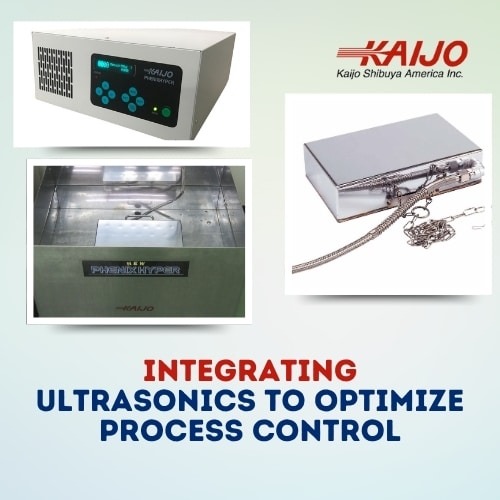
Process Control, Chemistry, and Operator Safety
Getting frequency, chemistry, and exposure time right determines whether ultrasonic cleaning improves assembly reliability or introduces new failure modes.
Process Parameter Reference
| Assembly Type | Typical Frequency | Temperature | Cleaning Time | Chemistry | Kaijo System |
| General PCB / SMT | 38 kHz | 50–60°C | 5–10 min | pH-neutral aqueous detergent | Phenix+ |
| High-density PCB / SMT (moderate standoff, higher contamination load) | 78 kHz | 45–55°C | 5–8 min | Electronics-compatible flux remover | Phenix Hyper |
| High-density PCB / SMT (fine-pitch, low-standoff, sensitive components) | 100–160 kHz | 45–55°C | 5–8 min | Electronics-compatible flux remover | Phenix Legend II |
| Precision / hybrid / sensor | 100–160 kHz | 40–50°C | 3–7 min | Deionized water + mild detergent | Phenix Legend II |
| Power modules / heavy flux | 26 kHz or 38 kHz | 55–65°C | 8–12 min | Alkaline flux remover (validated) | Phenix+ |
Chemistry Risk
⚠️ Using an ultrasonic cleaner for electronics amplifies both cleaning efficiency and chemical interaction. Chemistries that appear safe during manual cleaning can damage solder joints, coatings, polymers, and PCB substrates when energized ultrasonically. Never introduce acidic or alkaline solutions that are not specifically qualified for ultrasonic electronics cleaning. Avoid chemistries containing metal cations, chelating agents, or halides — each can leave conductive residue on board surfaces.
pH-neutral detergents are safe for most solder masks. Alkaline flux removers are effective for rosin-based flux but require validation against your specific component set before production use.
Operator Safety
- Use gloves and safety goggles when handling cleaning solutions
- Install local exhaust ventilation for fumes above open cleaning tanks
- IPA and similar volatile solvents create hazardous locations – their use requires explosion-proof equipment, proper classification, and controlled ventilation
- Ground ultrasonic units and use GFCI outlets; use antistatic mats and wrist straps for ESD-sensitive assemblies
Need help matching these parameters to your specific assembly or contamination profile? Kaijo’s technical experts can review your process requirements and recommend the right configuration.
Request a Free Process Review with Kaijo’s Experts
How to Use an Ultrasonic Cleaner for Electronics
The following steps outline how to configure and operate an ultrasonic cleaner for electronics safely and in accordance with IPC cleanliness requirements.
- Determine Component Suitability
Not all electronic components tolerate ultrasonic exposure. Evaluate assembly drawings and component datasheets before processing.
⚠️ Components to evaluate before ultrasonic cleaning:- Quartz crystals and oscillators (operate near ultrasonic frequencies — high damage risk)
- MEMS devices
- Sealed board-mounted relays
- Electrolytic capacitors (fully discharged before immersion)
- Piezoelectric devices operating near the selected cleaning frequency
- Select Frequency and Power
Use the process parameter table above as the starting point. The correct frequency depends on assembly density and component sensitivity. See the three-tier frequency guide in the table. For sensitive PCBs, begin at 50–70% power and validate before full production runs. - Select Compatible Chemistry
Use electronics-qualified, ultrasonic-compatible formulations. Check that detergents do not contain metal cations, chelating agents, or halides. - Set Time and Temperature
Run 5–10 minute cycles depending on the contamination level. Allow breaks between repeated cycles to avoid thermal stress on components. - Rinse and Dry
Rinse with deionized water after cleaning. Ensure thorough drying — residual moisture between component leads is a reliability risk, not a cosmetic one. - Validate Cleanliness
Method Standard Acceptance Threshold Ionic Contamination (ROSE) IPC-J-STD-001 Typical industry guideline is <1.56 μg/cm² NaCl equivalent, though stricter limits may apply in some applications. Surface Insulation Resistance (SIR) IPC standard > 108 ohms Visual Inspection Per customer / IPC spec No flux residue, bridging, or discoloration
Ready to validate ultrasonic cleaning for your production line? Request a sample cleaning trial. Kaijo’s experts will evaluate your assemblies and provide parameter recommendations before your first production run.
Request a Sample Cleaning Trial
Kaijo’s Differentiation in Electronics Cleaning
Kaijo brings over 65 years of ultrasonic engineering experience to specifying and supporting every ultrasonic cleaner for electronics application, with factory-direct technical support from Santa Clara, California. Unlike catalog suppliers, Kaijo engineers specify systems based on your board design, component configuration, contamination type, and production throughput — then work with your team through sample trials, parameter optimization, and process qualification documentation.
Phenix+ (26 kHz or 38 kHz, up to 1200W)
Low-frequency ultrasonic generator for general PCB cleaning and heavy flux removal on power assemblies. Suited to standard SMT boards, IGBT modules, motor control assemblies, and high-current components where high-energy cavitation is required to address robust contamination profiles.
Phenix Hyper (78 kHz, 1200W)
Operates in standard sweep frequency mode or Hyper Wave mode for three-dimensional cavitation distribution. The mid-range frequency makes it the right system for high-density assemblies with moderate standoff heights and higher contamination loads, where 38 kHz carries a risk of component damage and 100–160 kHz may not deliver sufficient cleaning energy. Hyper Wave mode distributes cavitation uniformly across complex board geometries and irregular surface profiles.
Phenix Legend II (100kHz / 130kHz / 160kHz)
High-frequency generator and transducer set for precision cleaning of high-density PCBs with fine-pitch or low-standoff components, hybrid circuits, sensor modules, and soft metals, and specified when 78 kHz output is too aggressive for component sensitivity requirements.
Engineering collaboration includes:
- Review of board design, BOM, and contamination profile
- Frequency, power density, and chemistry specification
- Rinse and drying protocol development
- Sample cleaning trials before production qualification
- Documentation support for process validation records
Request a process consultation. Kaijo’s engineers will evaluate your PCB assemblies or electronic components and recommend an ultrasonic cleaner for electronics with the appropriate frequency, power, and chemistry for your application.
Request a Process Consultation
Articles & Resources
Learn more about ultrasonic cleaners for electronics manufacturing
Frequently Asked Questions about Using Ultrasonic Cleaners for Electronics
Yes — when frequency, power density, and chemistry are correctly specified for the assembly. Evaluate component datasheets before processing, particularly for quartz oscillators, MEMS devices, and sealed relays. Validate parameters on representative assemblies before production implementation.
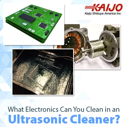
PCB assemblies, SMT boards, connectors, pin headers, terminal blocks, cable assemblies, sensor modules, hybrid circuits, and power electronics modules. Sealed relays, MEMS devices, and piezoelectric components near the cleaning frequency require individual evaluation.
There are three frequency tiers for electronics cleaning:
- 38 kHz — general PCB and SMT assemblies with robust components and standard standoff heights
- 78 kHz — high-density assemblies with moderate standoff heights and higher contamination loads, where 38 kHz carries component damage risk
- 100–160 kHz — high-density assemblies with fine-pitch or low-standoff components, precision hybrid circuits, and sensitive configurations where any excess cavitation energy creates damage risk
Use ionic contamination (ROSE) testing per IPC-J-STD-001 — the typical industry acceptance limit is below 1.56 µg/cm² NaCl equivalent, though stricter limits may apply in some applications. Surface Insulation Resistance (SIR) testing should return values above 10⁸ ohms. Visual inspection per your customer or IPC specification completes the validation protocol.
The Phenix III operates at 26 kHz or 38 kHz — suited to general PCB cleaning and heavy flux removal on power assemblies with robust components. The Phenix Hyper operates at 78 kHz with Hyper Wave mode — suited to high-density assemblies with moderate standoff heights and higher contamination loads where uniform cavitation distribution across complex board geometries is required. The Phenix Legend II operates at 100kHz, 130kHz, or 160kHz — suited to high-density assemblies with fine-pitch or low-standoff components, hybrid circuits, and sensitive configurations requiring high-frequency, low-energy cavitation.
Use gloves, safety goggles, and local exhaust ventilation. Ground the unit and use GFCI outlets. IPA and volatile solvents require explosion-proof equipment and hazardous location classification. Select electronics-qualified cleaning formulations designed specifically for ultrasonic applications.