



Ultrasonic Circuit Board Cleaner: Removing Flux Residues and Ionic Contamination That Spray-Wash Systems Miss
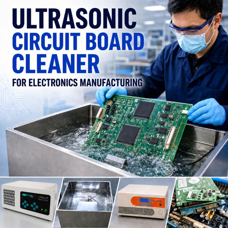
An ultrasonic circuit board cleaner removes flux residues, ionic contamination, and particulates from PCB assemblies using cavitation energy, giving process and manufacturing engineers a repeatable, non-contact cleaning method suited to the geometry and component-sensitivity demands of high-density electronics production. This page covers how the process works, which contaminants it removes, the parameters that determine cleaning success, and how to evaluate fit for your production environment.
How Ultrasonic Circuit Board Cleaning Works
At the core of every ultrasonic circuit board cleaner is cavitation, the rapid formation and implosion of microscopic bubbles generated by high-frequency sound waves passing through a liquid. When these bubbles collapse against contaminated surfaces, they release focused mechanical energy that dislodges flux residues, ionic contamination, and particulates from areas that spray-wash systems and manual scrubbing cannot reach, including beneath low-standoff components, inside blind vias, and along tightly spaced IC pins. An ultrasonic circuit board cleaner provides superior cleaning of intricate PCBs, ensuring every component is effectively cleaned.
Because the assembly is fully immersed, ultrasonic cleaning technology reaches every surface the liquid contacts without mechanical contact. This is the fundamental difference from spray washing: energy delivery is physics-driven and geometry-independent.
Frequency Selection: The Most Important Process Decision in PCB Cleaning
Choosing the right ultrasonic circuit board cleaner and frequency is essential for maintaining the integrity of your electronic components. Frequency controls the size and energy intensity of cavitation bubbles and determines whether the cleaning process removes contamination or damages the assembly. Matching frequency to assembly density and component sensitivity is not optional – it is the first engineering decision that must be confirmed before production parameters are set.
- 26–38 kHz— Large, high-energy bubbles for robust assemblies with heavy contamination and standard standoff heights. Effective on dense flux deposits but too aggressive for fine-pitch or low-standoff components.
- 78 kHz— Moderate bubbles that penetrate blind holes, tight geometries, and densely populated boards without the energy intensity that risks component damage at lower frequencies. The right choice is when 38 kHz carries a risk of damage, and 100–160 kHz may not deliver sufficient cleaning energy.
- 100–160 kHz — Small, low-energy bubbles for fine-pitch components, low-standoff configurations, wire bonds, and sensitivity-critical assemblies. Specified when the 78 kHz output is too aggressive for component sensitivity requirements.
Benchtop vs. Industrial Ultrasonic Cleaners
Benchtop units are adequate for low-volume or R&D applications but lack the power density, frequency precision, and process control required for production electronics manufacturing. Industrial ultrasonic cleaners provide calibrated output, uniform energy distribution across the cleaning tank, and configurable parameters, the foundation of a validated, repeatable cleaning process that meets IPC documentation requirements. With an industrial system, engineers can set and hold specific power levels, temperatures, and exposure times, then reproduce those exact conditions batch after batch.
For a broader overview of ultrasonic cleaning applications in electronics manufacturing, see Kaijo’s Ultrasonic Cleaner for Electronics Manufacturing resource.
Contaminants Removed from PCB Assemblies
The ultrasonic circuit board cleaner is particularly effective against a range of contaminants that can compromise the performance of electronic assemblies. An ultrasonic printed circuit board (PCB) cleaner is specified when the contamination profile exceeds the capabilities of aqueous spray or manual methods, particularly on assemblies where component geometry restricts access for cleaning.
Flux Residues
SMT, wave, and selective soldering all leave flux residues that, if not removed, degrade surface insulation resistance and promote electrochemical migration over time. No-clean flux does not mean no cleaning required. Residue beneath low-standoff components or inside connectors can cause latent reliability failures under field conditions. Ultrasonic cavitation reaches these geometrically restricted areas completely. An ultrasonic circuit board cleaner effectively removes flux residues that traditional cleaning methods may overlook, ensuring optimal performance of electronic devices.
Ionic Contamination
Ionic residues from flux activators, handling, or process chemistry are invisible to the naked eye but fully measurable. They lower surface insulation resistance below IPC-J-STD-001 thresholds, accelerate corrosion in humid conditions, and reduce long-term assembly reliability. An ultrasonic cleaner for PCB assemblies removes ionic contamination from the entire board surface, including beneath components and within internal geometries that visual inspection cannot verify and that ROSE testing will flag if left in place. With an ultrasonic circuit board cleaner, ionic contamination is thoroughly eliminated, enhancing long-term reliability in electronic applications.
Particulates, Oils, and Handling Residues
Machining oils, cutting fluids, solder balls, and handling residues on connector contacts, housings, and electromechanical components all respond well to ultrasonic cleaning. Cavitation energy removes these contaminants from threaded inserts, pin contacts, and blind holes without mechanical contact, which could otherwise deform plated surfaces or alter dimensional tolerances.
Why Visual Inspection Alone Is Not Sufficient
Visual inspection cannot verify cleanliness to IPC standards. Ionic contamination testing (ROSE method per IPC-J-STD-001) and Surface Insulation Resistance (SIR) testing are required. The typical ROSE acceptance threshold is below 1.56 μg/cm² NaCl equivalent, with SIR values required above 10⁸ ohms. See the cleanliness validation table in the Process Parameters section below. The ultrasonic circuit board cleaner’s ability to reach confined areas makes it an indispensable tool for modern electronics manufacturing.
Process Parameters Engineers Must Control
Selecting the correct parameters determines whether an ultrasonic circuit board cleaner improves assembly reliability or introduces new failure modes. Each variable below is a process engineering decision, not a default setting.
-
- Frequency Match to assembly density and component sensitivity using the process parameter table below. Validate on representative assemblies before committing to production parameters. Investing in a quality ultrasonic circuit board cleaner can significantly extend the lifespan of your electronic components.
-
- Power Density and Exposure Time
Start at 50–70% power for sensitive assemblies as a recommended starting point and validate before production. Excessive power or extended exposure can stress solder joints and component packages. When using an ultrasonic circuit board cleaner, it is crucial to monitor the cleaning parameters to optimize performance.
- Power Density and Exposure Time
- Bath Temperature Typical operating range is 40–65°C, depending on assembly type and chemistry. Higher temperatures improve flux solubility but increase chemical reactivity — control both together.
- Rinse and Dry Rinse with deionized water after cleaning. Thorough drying is a reliability requirement; residual moisture between components leads to a failure risk, not a cosmetic issue.
Process Parameter Reference by PCB Assembly Type
Employing an ultrasonic circuit board cleaner ensures that no contaminants remain that could lead to electronic failures.
| PCB Assembly Type | Frequency | Temperature | Cleaning Time | Chemistry | Kaijo System |
|---|---|---|---|---|---|
| Standard PCB / SMT (robust components, standard standoffs) | 38 kHz | 50–60°C | 5–10 min | pH-neutral aqueous detergent | Phenix+ |
| High-density PCB / SMT (moderate standoffs, higher contamination) | 78 kHz | 45–55°C | 5–8 min | Electronics-compatible flux remover | Phenix Hyper |
| Fine-pitch / low-standoff / sensitivity-critical PCB assemblies | 100–160 kHz | 45–55°C | 5–8 min | Electronics-compatible flux remover | Phenix Legend II |
| Hybrid circuits/sensor modules/precision electronics | 100–160 kHz | 40–50°C | 3–7 min | DI water + mild detergent | Phenix Legend II |
Cleanliness Validation Reference
| Validation Method | Standard | Acceptance Threshold |
|---|---|---|
| Ionic Contamination (ROSE) | IPC-J-STD-001 | < 1.56 μg/cm² NaCl equivalent (stricter limits may apply) |
| Surface Insulation Resistance (SIR) | IPC standard | > 10⁸ ohms |
| Visual Inspection | IPC spec/customer | No flux residue, bridging, or discoloration |
Chemistry Selection: A Process Control and Safety Decision
Ultrasonic energy intensifies chemical reactivity. Chemistries that appear safe in manual cleaning can damage solder joints, solder masks, polymers, inks, coatings, and PCB substrates when energized ultrasonically. Chemistry selection is a critical engineering decision, not an afterthought.
Recommended:
- pH-neutral aqueous detergents formulated specifically for ultrasonic electronics cleaning, safe for most solder masks
- Alkaline flux removers validated against your specific component and solder mask set (effective for rosin-based flux)
- Deionized water rinse following all cleaning cycles
Avoid:
- Acidic or alkaline solutions not specifically qualified for ultrasonic electronics use
- Chemistries containing metal cations, chelating agents, or halides — these leave conductive residue on board surfaces
- Chemistries prone to aerosolization, excessive vapor generation, or skin contact risk in open ultrasonic baths
IPA and volatile solvents require explosion-proof equipment and NEC Article 500 hazardous location classification — their operational requirements often outweigh their cleaning advantages in production environments.
Operator Safety Requirements
- Wear chemical-resistant gloves and safety goggles when handling cleaning solutions
- Install local exhaust ventilation above all open cleaning tanks
- Ground ultrasonic units and connect to GFCI-protected outlets
- For ESD-sensitive assemblies: use antistatic mats and grounded wrist straps
- IPA and similar volatile solvents create hazardous locations — their use requires explosion-proof equipment, NEC Article 500 classification, and controlled ventilation
Chemistry validation is application-specific. Kaijo’s engineers can review your assembly type, solder mask, and contamination profile to confirm compatibility before your first production run.
Request a Free Process Consultation
Evaluating Ultrasonic Cleaning for Your Production Environment
Before specifying an ultrasonic circuit board cleaner for production, engineers need to evaluate four factors: production volume and throughput requirements; validation and quality control protocols; operator safety and compliance obligations; and whether specific component types require individual evaluation before cleaning.
Production Volume and Throughput
Batch ultrasonic systems support low- to mid-volume production, where assemblies are cleaned in groups. Inline configurations support higher-throughput lines that require continuous processing. Kaijo engineers can specify the right system architecture to meet your throughput targets — from R&D-level batch cleaning to full production-line inline integration.
Validation and Quality Control
Ultrasonic cleaning is a validated process. ROSE testing per IPC-J-STD-001, SIR testing, and visual inspection provide the cleanliness documentation required for high-reliability electronics manufacturing. Kaijo offers sample-cleaning trials and process-qualification documentation — so engineers have the data they need before committing to production parameters.
Operator Safety and Compliance
Using an ultrasonic circuit board cleaner is vital to maintaining compliance with industry standards. Chemistry handling, ventilation requirements, and equipment grounding all require documented procedures. These are standard practices in production electronics environments. Kaijo’s engineers include safety protocol guidance in the process specification.
When Ultrasonic Cleaning May Not Be Appropriate
Assemblies with quartz oscillators, MEMS devices, sealed relays, or piezoelectric components operating near the cleaning frequency require individual evaluation. These components may require alternative cleaning methods or frequency-specific validation before production use. Kaijo engineers evaluate these cases as part of the process specification review — before any trial cleaning is conducted.
Learn more about ultrasonic cleaning applications in electronics
Kaijo’s Industrial Ultrasonic Cleaners for Circuit Board Cleaning
Kaijo’s engineers specify systems based on your board design, component configuration, contamination profile, and production throughput — not catalog defaults. Factory-direct technical support from Santa Clara, California, means your process questions reach the engineers who designed the system, not a reseller. With over 70 years of ultrasonic engineering experience, Kaijo works with your team through sample trials, parameter optimization, and process qualification documentation. Kaijo’s ultrasonic circuit board cleaner systems are designed for efficiency and effectiveness in high-volume applications.
Phenix+ (26 kHz or 38 kHz, 600W or 1200W)
The Phenix+ is an energy-efficient industrial ultrasonic generator well-suited for general PCB cleaning and flux removal on standard assemblies and electromechanical components, where controlled low-frequency cavitation is required. Its auto-tuning and auto-calibration functions maintain consistent output efficiency as load conditions change, eliminating the need for field recalibration when swapping transducer arrays. Four programmable output steps, an adjustable sweep frequency, and a touch-screen interface give process engineers precise, repeatable control over cleaning parameters from cycle to cycle.
Phenix Legend II (100 kHz / 130 kHz / 160 kHz)
The Phenix Legend II delivers high-frequency, low-energy cavitation for precision cleaning of populated PCB assemblies with fine-pitch or low-standoff components, hybrid circuits, sensor modules, and sensitivity-critical configurations. Specified when 78 kHz output carries component damage risk — it removes flux residues and ionic contamination without stressing wire bonds, die attach, or ceramic substrates.
Phenix Hyper (78 kHz, 1200W)
The Phenix Hyper operates in standard sweep frequency mode or Hyper Wave mode to achieve a three-dimensional cavitation distribution — eliminating dead zones and energy gradients that cause inconsistent cleaning results across a batch of boards with varying surface profiles. Well-suited to higher-throughput production environments and high-density PCB assemblies with moderate standoff heights and higher contamination loads.
Engineering Collaboration Includes:
An ultrasonic circuit board cleaner is designed to clean various types of electronic assemblies and is tailored to specific cleaning needs.
- Review of board design, BOM, and contamination profile
- Frequency, power density, and chemistry specification
- Rinse and drying protocol development
- Sample cleaning trials before production qualification
- Documentation support for process validation records
Not ready for a consultation? Start with a sample cleaning trial. Send Kaijo’s engineers a representative assembly and receive cleaning results, along with recommended process parameters, before you commit to a production specification. Try our ultrasonic circuit board cleaner to experience the benefits of advanced cleaning technology.
Request a Sample Cleaning Trial
Articles & Resources
Learn more about ultrasonic cleaning for PCBs and electronic components:


Request a Process Consultation — Kaijo’s experts will evaluate your PCB assemblies and recommend frequency, power, and chemistry parameters for your specific application.
Request a Free Process Consultation
Frequently Asked Questions: Ultrasonic Circuit Board Cleaner
Yes — when frequency, power density, and chemistry are correctly specified for the assembly. Review component datasheets before processing, particularly for quartz oscillators, MEMS devices, sealed relays, and piezoelectric components operating near the cleaning frequency. Validate parameters on representative assemblies before production implementation.
Use electronics-qualified, ultrasonic-compatible formulations. pH-neutral aqueous detergents are safe for most solder masks. Alkaline flux removers are effective for rosin-based flux but require validation against your specific component set. Avoid chemistries containing metal cations, chelating agents, or halides, and never introduce acidic or alkaline solutions not specifically qualified for ultrasonic electronics use.
Yes. Removing ionic contamination and flux residues reduces the risk of electrochemical migration, insulation resistance degradation, and corrosion under humidity — failure mechanisms that develop over time and are difficult to diagnose after assembly. Ultrasonic cleaning addresses these failure modes at the source, before conformal coating or final integration.
Ionic contamination (ROSE) testing per IPC-J-STD-001 confirms ionic residue levels are below 1.56 μg/cm² NaCl equivalent (stricter limits may apply). SIR testing should return values above 10⁸ ohms. Visual inspection per customer or IPC specification completes the protocol. Kaijo provides documentation support for process qualification records as part of the engineering collaboration.
The Phenix Legend II, Phenix Hyper and Phenix+ systems deliver precise, calibrated ultrasonic output with uniform energy distribution across the cleaning tank. Both are specified through a collaborative engineering process matched to the specific assembly type, contamination profile, and production requirements.